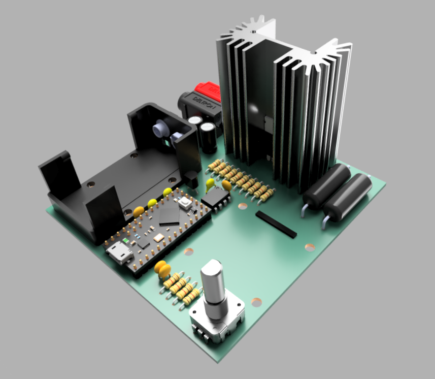
A bench-top power supply I designed and built for the test and development of other projects. This project has been one of my biggest projects to date. It was the impetus that taught me about basic electronics.
This project is currently a work in progress. I am actively using version 2 and working on version 3 of the design.
I was the sole designer on this project. I learned a large portion of my fundamentals from this project, including circuit basics like resistors, capcitors, inductors, op-amps, transistors, etc. I also learned basic building blocks like current regulators, amplifiers, voltage references, etc. The main resources used for this project was YouTube (in particular EEVBlog) and electronics forums (like EEVBlog forum).
A constant current dummy load designed to test power supplies. It’s capable of sinking up to 3A and ~15 Watts. This project was inspired by Dave Jone’s (EEVBlog) episode #102. It was also heavily influenced by the discussion at the EEVBlog forum.
I was the sole designer on this project. I learned a lot about system stability and oscillating amplifiers (a common problem in EE design) from this project. The main resources were the above mentioned EEVBlog, the lab equipment available on campus, and Dr. Neihart at Iowa State University.
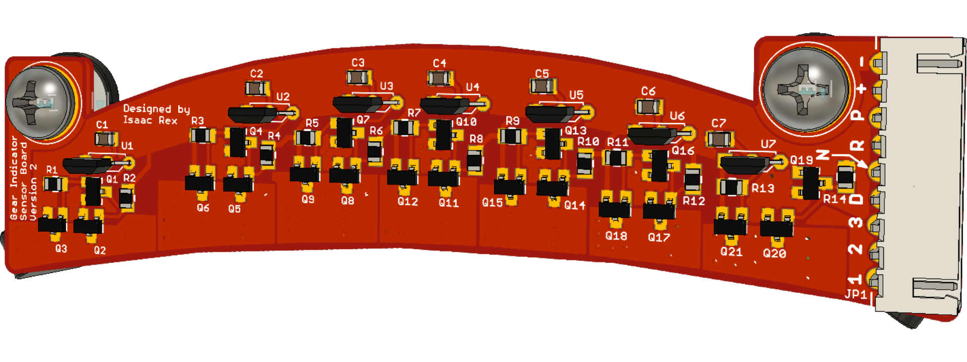
This is a project to improve the lighting for the gear shifter on my 1984 Camaro. The OEM lighting solution was a single incandescent bulb that lit up the gear letters. This project was to indicate the gear by lighting up specifically the gear that the car is in. It’s a two board project with the sensor board and the control/LED board.
I was the sole designer on this project. This project taught me how to use a CNC mill for milling the board and general shape. I also learned about system level design as this project has three interconnected boards and works with a larger system. The main resources used were a family friend’s machine shop and online electronics tutorials.
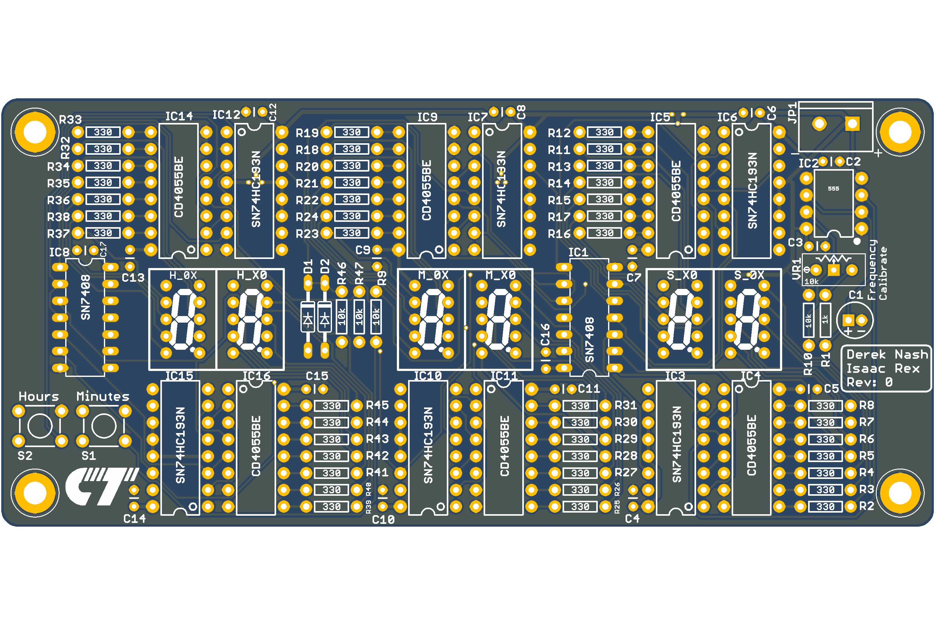
This was a team project building a clock from discrete digital logic chips. It uses a 555 timer as the clock source, binary up-counters, and binary to 7-segment decoders.
My main role in this project was circuit designer and PCB layout. I learned a lot about doing group projects and dealing with failure on this project. The primary resources for this project were the standard engineering tools, including breadboards, test and measurement equipment, and PCB design tools.


